Quantcast
Channel: Codes OBD2 – Sparky's Answers
Viewing all 15 articles
Browse latest View live

2003 Chevrolet Silverado, Changing the Mode Actuator, Code B0263

$
0
0

DSC04774

This 2003 Chevrolet Silverado came in with the air flow stuck on defrost. A simple diagnosis of a code B0263 found a faulty mode actuator.  This repair applies to 2003, 2004, 2005, 2006, 2007, 2008, 2009, 2010, and 2011 Chevrolet Avalanche, Silverado, Suburban and Tahoe. It also applies to Cadillac Escalade, GMC Sierra and Yukon for the same year models.

It is specific to all models WITH auto a/c controls.

Models with manual a/c controls, WITHOUT a factory floor mounted center console.Trucks that have manual a/c controls and  WITH a factory floor mounted center console, use a slightly different actuator and procedure. On that model the gear/cog seperates from the actuator. Before removing that actuator use something to hold the gear/cog in place while the actuator is being removed. If it comes off, it will take some time to figure out where the gear/cog and the three levers go. I hope to do a post on that model soon.In the meantime, if you need to order this part for a full sized truck or suv, that has manual a/c controls and a factory floor mounted center console (RPO Code D07), that is not shown in this post, please click here.

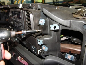
Now onto this repair.The actuator is located under the driver's side of the dash, above the gas pedal area, and on the end of the heater a/c case.

I know this will seem quite simplistic but the very first thing I do during this repair is, to push down the parking brake pedal. I cannot turn under the dash with it up.

Then either by hand or using the tool shown in the pictures, I pull the retaining pin out that holds the heater duct in place.

A better view of the retaining pin.

This is the view of the heater vent with the extension removed. The actuator is above the duct. Inn case you are wondering the piece in the duct is the duct temperature sensor.

A better view. I had to place the camera behind the brake pedal so the angle is slightly different from what you will see. There are two 5.5 mm headed screws that hold the actuator in place. The upper screw also holds the wiring harness retaining clip as well. I have pictures of that later. Try to set the old actuator to the same position as the new one before removing. To do this switch the ignition on and have someone depress the defroster button for you. While looking at the slot on the center shaft also have one hand on the ignition switch. Turn the ignition off just before the slot lines up with the appropriate hash mark. If this is not possible for you just set the controls to the split defrost and floor position.  This will make it easier to slip the actuator out. Lift the edge of the actuator, that is closest to the firewall, away from the heater a/c case. It can take a good bit aof patience and manipulation to remove the old actuator. So take your time and don't caveman it out.

This enables the large cog to come out from under the pin on the white lever gear. Remember which slot it was in, the inner one.

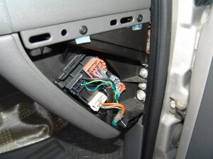
Now that the actuator is out of the way, you can see the two door levers. The small black one to the left is for the defroster door. The larger white one with the gear teeth attached is for the vent / floor door.

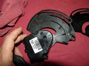
The old actuator on the left and the new one on the right.

Note the position of the actuator cog to the actuator motor.  The actuators come prepositioned to allow for easier assembly. Do not connect the wiring to the actuator until the new actuator is installed. If you do for some reason, refer back to this picture to reindex the actuator to the correct position.
To purchase a new actuator please click here.

Slide the new actuator into place in the reverse order that you pulled it out. Once it is generally back in place make sure that the peg on the back side of the white gear lever is in the inner slot of the actuator cog. Then while holding it gently in place reach up to the top side of the cog and make sure that the defroster lever is in its slot under the cog.  Now take your time and gently maneuver the actuator around until the actuator drops completely into place. The two door lever pins have to be lined up. The actuator has to be lined up with the two mounting bosses,  the center rings on the actuator cog and the heater a/c case also have to be lined up. Remember patience and gentle maneuvering and it will drop that last little 1/4" to  3/8" to the mounting bosses. Do not force or use the screws to draw it down. You will likely break something or have a jammed actuator at the very least.

Remember when installing the mounting screws that the upper screw hold down the wiring harness retainer clip.

I used a 1/4" palm ratchet and  5.5 mm deep well socket to remove and install the screws.

The new actuator installed.

This truck has auto a/c controls. The part and the basic repair are the same whether it has manual or auto controls. I have not done one on the newer body style truck but I would assume at this point it will be similar. This repair of course should be generally the same for 2003 through 2007 Classic series trucks and suvs.

Remember to preset the controls to the split defrost / floor position before removing the old actuator. If needed, use a small screwdriver or the edge of a quarter to rotate the actuator into the correct position. Once in place disconnect the wiring at the actuator. If you are manually assisting the actuator, you must do it withing the first minute or two of switching the ignition on. The system will try to adjust to the commanded position for a minute and then stops trying. At that point the motor will not be able to be assisted. The ignition will need to be  turned off for at least ten seconds and then back on for another attempt.

To perform a recalibration of the newly installed actuator, I used a Tech 2 scan tool. If you do not have a scan tool you have two choices. Remove the fuse shown below for one minute or disconnect the battery for one minute. After the fuse is installed or the battery is reconnected, start the engine and let it run for at least one minute (I prefer the old time of 4 minutes). DO NOT TOUCH the a/c controls during this time. Turn the ignition off for at least ten seconds. Restart the engine and check the a/c operation.

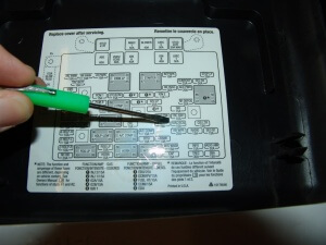
The fuse location  and name may be different for other vehicles. This of course is a 2003 Silverado.

Please look closely at the picture below so that you can identify where the two door levers are. I have had some people tell me that there is only one. The defroster lever has a pin sticking up that has to be aligned in a closed slot in the under side of the actuator cog. The white vent/floor gear lever has a pin on the underside that must drop into the inner open slot in the actuator cog. The gear teeth should self align when the actuator is moved.

I am building a test procedure for this actuator. Current testing is as follows.

At the mode actuator, with the ignition switched on, check for battery voltage on the brown wire.

Check for a 5 volt reference signal on the light blue/black wire.

The yellow wire should show ground as it is the reference low signal from the control head assembly.

The light green wire should have a variable 0-5 volt signal on it. This is the actuator position signal.

The tan wire is the command signal wire. There should be one of three voltages present as different modes are commanded.

5 volt signal is the command for counter clockwise rotation.

2.5 volt signal is the stop command.

0 volt command is  for clockwise rotation.

I have found through bench testing an actuator that there is a nominal 2.5 volt output from the actuator on the tan wire. The control head therefore must apply a ground on the tan wire to reduce the voltage to zero to command clockwise rotation. It must also apply voltage to bring the reading to 5 volts in order to command counter clockwise rotation.

All voltages referred to above should be considered nominal volts. In testing, I found that a variation of .75 volts from the 2.5 volt stop command was enough to move the actuator.

When doing testing, if you find no variation on the tan wire, do not jump to the conclusion that the control head is faulty. The system will go into a "sleep mode" if a hard fault is found with an actuator. The system will determine this within a minute or two of turning the ignition on. You have to have your meter set up and ready to see the reading before you actually turn the key on. You may also have to clear hard fault codes before the system will even try to move the affected actuator. You can clear the codes with a scan tool, remove the HVAC memory fuse or disconnect the battery.

If any of the signals are missing, check the wiring at the right and left junction boxes at either end of the dash. Look for signs of corrosion, general looseness or fretting. Locations can vary from year to year and model to model. Please consult a wiring diagram.

The post 2003 Chevrolet Silverado, Changing the Mode Actuator, Code B0263 appeared first on Sparky's Answers.


2004 Chevrolet Silverado, Dash Cover Removal

$
0
0

DSC04853

This 2004 Chevrolet Silverado came in with multiple hvac actuator faults. After diagnosing a faulty passenger side blend air door actuator with my Tech 2 scan tool it was time to remove the dash cover. Not a big deal but there are a lot of steps.

Lift the lower edge of the dash end caps and remove the covers.

There are two phillips headed screws. A short screw driver is needed to do this. Remember to do this on both sides of the dash.

Using a small screw driver or other similar device, gently pry the passenger side vents from the dash.

Work the vent out evenly. If it is cocked to one side or the other it will tend to jam.

There is a phillips headed screw under each vent on the passenger side.

Repeat the process on the other vent.

Now, look up into the upper edge of both vent holes. You will see a white push button. Depress the buttons. The buttons depress to the center of the handle assembly. The right side pushes to the left  and the left side pushes to the right.

Pull the passenger handle from the dash. You can alternate from side to side until it is fully removed or you can have someone assist you.

Grasp the upper edge of the trim panel and pull out. Once the upper edge is released, work the panel up until it releases from the dash panel.

Rotate the panel over to expose the tweeter wiring, if present. Depress the locking tab and pull the connectors apart.

Grasp the upper edge of the dash face panel and pull it loose from the dash.

Work around the dash face until all of the clips are free. Tilt the steering wheel fully down. Turn the ignition on and drop the shifter handle all of the way down. Roll the upper edge of the dash face out towards you. The panel will have to be flexed above the center of the instrument cluster to release the face panel fully.

A better view of releasing the "A" pillar trim panel.

Remove the 7 mm headed screws around the edge of the dash cover panel.

Once all screws are removed, the dash cover will pull off of the dash carrier. It has to be pulled away from the windshield to release the forward clips. Then lifted slightly to clear the leading edge of the dash carrier.

Most trucks will have the ambient light sensor and possibly a sun load sensor mounted to the underside of the dash.

The ambient light sensor twists out like a light bulb. Be gentle with this part as it is fragile. If it has the second sensor, it has to be unplugged.

Support the dash cover evenly as you pull it from the vehicle.

Now , remove the two 7 mm screws that hold the right driver's side vent register in place. Remove the vent register.

Remove the panel holding the passenger side airbag switch. The panel may be blank in some years. It pulls out and uses spring clips to hold it in place.

Now, if you look under the vent duct you will see the wiring for the passenger side blend air door actuator.  Look closely and you should see the actuator itself.

This post is so long that I am breaking it up into multiple posts.

To see how to change the recirculation / fresh air door actuator please click here.

To see how to change the passenger side blend air door actuator from this point,  please click here.

The post 2004 Chevrolet Silverado, Dash Cover Removal appeared first on Sparky's Answers.

2004 Chevrolet Silverado, Changing The Passenger Side Blend Door Actuator, B0424

$
0
0

DSC04875

This 2004 Chevrolet Silverado came in with a faulty passenger side blend door actuator. In the last post I got you to this point. If you have not yet read that post please click here. Now that the dash cover is off and you can see the actuator, but you still cannot get to it. More things need to come apart.

Remove the wiring hold down clips from the metal brackets as shown below.

Remove the 7 mm headed screws from the brackets on the passenger side.

Using a ratchet remove the two 10 mm headed screws from the front edges of the bracket on the passenger side.

Remove the 7mm  screw from the driver's side of the cross over bracket.  Remove  the bracket.

Now the "U" shaped bracket on the passenger side can be removed.

Remove the 7 mm screws on the driver's side bracket. I also remove the two 10 mm bolts on the driver's side bracket to make sure the dash will move around freely.

Disable the air bag or SRS system according to the manufacturers directions. Then remove the two upper 10 mm bolts from the air bag as shown in the next two pictures.

Then remove the two lower air bag screws.

Note that the air bag screws are shorter than the bracket screws. Do Not put the long bolts back in the airbag when reassembling.

< Pull the orange "positive assurance clip" from the yellow connector. Disconnect the connector and remove the airbag. Use the manufacturers recommendations for handling and storing the airbag.

Getting close but more still has to come out. The silver box shown below is the vehicle communication interface module. It may not be present on all vehicles as it is related to the Onstar System.

There are three 10 mm nuts that hold the module to the brackets. They are locking nuts so they have to be wrenched all of the way off.

Remove the two 10 mm nuts at the passenger end of the dash carrier. Do Not mix these nuts up with the ones removed from the VCIM brackets.

Now remove the 7 mm screw from the backside of the right passenger vent.

Remove the 7 mm screw from the position shown below.

Wiggle the corner of the dash out as shown below.

I used a screwdriver handle to keep the duct work lifted.

I also used a pry bar to lift the duct work slightly to give myself more room. The weight of the pry bar is enough to keep the duct work up but you may want someone to hold it for you. If someone hold it for you be sure they do not use the area in the center of the opening for a fulcrum. It will break the mounting panel where the nut is for the phillips headed screw that was removed much earlier.

The VCIM can now be wiggled up and the wires disconnected.

Remove the wiring harness retaining clip from the bracket as shown below.

Remove the wiring harness clip from the cross bar as shown in the two pictures below. Lift the harness slightly to gain more room to work.

Using a short 5.5 mm socket and ratchet, remove the two mounting screws. Disconnect the wiring from the actuator before removing the screws. makes it a little easier.

You will actually need to work through two openings and use both hands to make it easier.

A magnet on a stick works real well fro retrieving dropped screws and  sockets.

You can finally remove the actuator from the dash.

Free at last.

The new and old actuators. The numbers match 52402588.
If you need to buy one of these actuators please click here.

If you do not have a Tech 2 or similar scan tool to diagnose these actuators, you can do voltmeter testing at these connectors. That is a whole other post though.

The post 2004 Chevrolet Silverado, Changing The Passenger Side Blend Door Actuator, B0424 appeared first on Sparky's Answers.

2005 GMC Sierra, Air Blows Only From Defroster Vents

$
0
0

DSC05430

This 2005 GMC Sierra came in with the complaint that the air will only flow from the defroster vents, regardless of where it is commanded to. This Sierra has auto a/c controls and no floor mounted center console.

Of course the customer brought the truck in, knowing that I had to lay under the driver's side of the dash and did not think to vacuum the floor board.

I checked the codes and sure enough there was a code B0263 stored in the HVAC module. Your scan tool has to be able to go into the body systems to see this information. A plain OBD2 scanner just won't do the job. This repair is so common that you can diagnose it by symptom if you have to. The most common symptom of course is lack of control over the vent output position and normally it will be stuck in the defroster only position. If it is not currently stuck in the defroster position but you are changing the actuator anyways. make sure that you set the vent position to defrost before starting this procedure. You will see why later.

The data lines show an actual mode door position and a commanded mode door position. They do not even come close to matching.

I laid a fender cover on the dirty floor and set the parking brake pedal. The pedal hits me in the shoulder and prevents me from being able to maneuver around.

Now I am ready to get in there and work.

I start by removing the push pin that holds the driver's floor vent extension in place.

With the push pin released the duct extensions pulls easily from the stationary duct.

The lower screw for the actuator is just above the duct work and cannot be seen. It has to be felt. 5.5 mm head

The second screw can be easily seen as it is at the upper edge of the actuator. Note that it also holds the wiring harness in place.

I have developed a slightly different twist to this repair procedure. I could not take good enough pictures  from under the dash so hopefully I can show you how on the bench and you can transfer that knowledge to the vehicle.

With the two mounting screws removed and the wiring disconnected, use your fingers and thumb as leverage to push the cam/cog from the actuator shaft. The goal is to leave the cam/cog in place on the end of the heater-a/c case and to remove the actuator motor only.

The old assembly on the left and the new one on the right.

The old assembly separated

Taking the new actuator motor and installing it on the old cam/cog. Remember these steps will be done under the dash. Except for removing the new actuator motor from the new cam/cog, that can be done anywhere. I am just doing this on a bench to give you a clearer idea of what has to be done.

The old cam/cog with the new actuator motor installed.  Note the positions of the cam/cog in relation to the motor. Assuming that your actuator has failed in the most common position, blowing out of the defroster vents only, you should not have to do anything other than installing the actuator motor. No indexing of the door shafts to the cam/cog or recalibration of the actuator motors. This is a big time saver.

If you need to purchase one of these actuators please click here.

I recently had to go behind someone that could not properly install the actuator. The actuator and cog were removed from the truck. I installed the cog with the upper peg inserted into the outer slot. I then moved the cog around so that the center/rotating boss dropped into it's mating position on the HVAC box. Installed the actuator onto the cog and bolted it down. Once connected and activated the actuator turned the cog counter clockwise and indexed the gear tooth lever perfectly. I was a little surprised by this so I tried it several times and every time it aligned properly. When looking at the white geared lever there is one long tooth and when rotated that long tooth should overhang the last black tooth on the cog.  Do Not forget that the actuator needs to be recalibrated in order to work correctly.  Please see the link on the left side bar of this site.

The post 2005 GMC Sierra, Air Blows Only From Defroster Vents appeared first on Sparky's Answers.

Actuator Replacement GM Trucks and SUV’s 1999-2009

$
0
0

This is a list of procedures to replace the multiple actuators on General Motors Trucks and SUV’s from 1999 to 2009.

These posts will apply to all of the Full Sized Trucks and SUV’s listed below. There may be slight differences between brands and trim levels.

HVAC Calibration Procedure GM Trucks And SUV’s

2003 Chevrolet Silverado, Changing The Mode Actuator, B0263

2004 Chevrolet Silverado,  Dash Cover Removal

2004 Chevrolet Silverado, Changing The Passenger Side Temperature Door Actuator

2004 Chevrolet Silverado, Changing The Mode Actuator

2004 Chevrolet Avalanche Changing The Fresh Air/Recirculation Door Actuator

2004 Chevrolet Tahoe, Driver’s Side Blows Hot Only

2005 Cadillac Escalade, Blows Hot Air Only From Driver’s Vents

2005 Cadillac Escalade Installing The Passenger Side Hush Panel

2005 GMC Sierra, Air Only Blows From Defrost

These posts will apply to to the midsized SUV’s listed below. There will be slight differences between brands and year models.  Year model 2002 mode actuators are different from all other years and so is the procedure. I have not had the opportunity to document one of these yet. If the vehicle has adjustable pedals the accelerator pedal assembly may have to be removed.

2003 GMC Envoy, No A/C Vent Control, B0263

2004 Chevrolet Trailblazer, Identifying The Heater- A/C Actuators On Driver’s Side

2002 Chevrolet Trailblazer, Poor Heat, Clicking Sound Under Driver’s Side Of Dash

HVAC Calibration Procedure GM Trucks And SUV’s

1999 Chevrolet 1500/2500 Pickup, New Body Style

1999 GMC 1500/2500 Pickup, New Body Style

2000 Chevrolet Silverado
2000 Chevrolet Suburban
2000 Chevrolet Tahoe
2000 GMC Sierra
2000 GMC Yukon

2001 Chevrolet Silverado
2001 Chevrolet Suburban
2001 Chevrolet Tahoe
2001 GMC Sierra
2001 GMC Yukon

2002 Cadillac Escalade
2002 Chevrolet Avalanche
2002 Chevrolet Silverado
2002 Chevrolet Suburban
2002 Chevrolet Tahoe
2002 Chevrolet Trailblazer
2002 GMC Envoy
2002 GMC Sierra
2002 GMC Yukon
2002 Oldsmobile Bravada

2003 Cadillac Escalade
2003 Chevrolet Avalanche
2003 Chevrolet Silverado
2003 Chevrolet Suburban
2003 Chevrolet Tahoe
2003 Chevrolet Trailblazer
2003 GMC Envoy
2003 GMC Sierra
2003 GMC Yukon
2003 Isuzu Ascender
2003 Oldsmobile Bravada

2004 Buick Rainier
2004 Cadillac Escalade
2004 Chevrolet Avalanche
2004 Chevrolet Silverado
2004 Chevrolet Suburban
2004 Chevrolet Tahoe
2004 Chevrolet Trailblazer
2004 GMC Envoy
2004 GMC Sierra
2004 GMC Yukon
2004 Isuzu Ascender
2004 Oldsmobile Bravada

2005 Buick Rainier
2005 Cadillac Escalade
2005 Chevrolet Avalanche
2005 Chevrolet Silverado
2005 Chevrolet Suburban
2005 Chevrolet Tahoe
2005 Chevrolet Trailblazer
2005 GMC Envoy
2005 GMC Sierra
2005 GMC Yukon
2005 Isuzu Ascender

2006 Buick Rainier
2006 Cadillac Escalade
2006 Chevrolet Avalanche
2006 Chevrolet Silverado
2006 Chevrolet Suburban
2006 Chevrolet Tahoe
2006 Chevrolet Trailblazer
2006 GMC Envoy
2006 GMC Sierra
2006 GMC Yukon
2006 Isuzu Ascender

2007 Buick Rainier
2007 Chevrolet Silverado Classic
2007 Chevrolet Trailblazer
2007 GMC Envoy
2007 GMC Sierra Classic
2007 Isuzu Ascender

2008 Chevrolet Trailblazer
2008 GMC Envoy
2008 Isuzu Ascender

2009 Chevrolet Trailblazer
2009 GMC Envoy

The post Actuator Replacement GM Trucks and SUV’s 1999-2009 appeared first on Sparky's Answers.

2005 GMC Sierra, Multiple Misfires

$
0
0

DSC06893

This 2005 GMC Sierra came in with a poor run condition and multiple misfire codes stored. Code P0304 was one of the misfire codes stored. While looking at data I noted that misfires on cylinder #4 were markedly higher that most of the other cylinders. Normally when confronted with high misfire counts on this engine style I would suspect a leaking fuel pressure regulator. Fuel would  be leaking fuel though it's diaphragm into the attaching vacuum line that happens to enter the intake just above cylinder #4. Not the case in this situation. Notice how the number four spark plug wire appears to be pulled tight.

A close inspection of the wire and boot revealed a carbon track on the top of the spark plug wire boot. Just above where the wire enters the boot. Click on the next picture to enlarge for a better view.

Although this problem was easily diagnosed with a scan tool, I wanted to show some more simplistic ways of finding a misfire. Water is a great diagnostic tool for finding leaking spark plug wires. Many times I diagnose faulty spark plug wires by asking the customers the right questions. Does it run bad first thing in the morning? Water in the form of dew plays a part in morning misfires. Was it running bad the other day when it was raining? Running poorly on a rainy day but running well a day or two after the rain stops is a clear indicator of leaking spark plug wires. Well let's introduce some water to this situation and see what happens.

If you will enlarge the next pictures I am pretty sure you will be able to see the misfire in progress. Notice how the appearance of the spark changes as the amount of water decreases. A faint orange glow in the small puddle of water on top of the spark plug boot.

A bright orange spark.

A faintly orange, mostly white spark. When the moisture evaporated away the misfire went with it. Of course that was at idle with no load on the engine also.

Another way to find leaking spark plug wires is to attach one end of a wire to a screwdriver and attach the other end to battery ground. Then move the screwdriver tip along the spark plug wire in question. Look and listen for spark jumping to the screwdriver tip.

The fix for this truck was just a replacement of spark plugs and spark plug wires.

The post 2005 GMC Sierra, Multiple Misfires appeared first on Sparky's Answers.

2004 Chevrolet Silverado, Changing The Mode Actuator

$
0
0

DSC07508

This 2004 Chevrolet Silverado came in with the complaint that the air only blows through the defrost  and will not blow out of any other location. There were codes B0263 and B3770 stored in the HVAC module. The codes refer to mode actuator faults.

To access the actuator, the driver's side heater floor vent extension has to be removed. There is a single push pin that holds it on.

With the push pin removed from the vehicle the vent extension can be dropped down and pulled off of the main heater- a/c case.

The actuator is located above the driver's floor vent at the heater case. There are two 8 mm headed screws that hold the actuator to the main assembly. The 8 mm  screws are used if the system has manual controls but has a factory floor mounted center console. If the system had automatic controls or there was not a factory installed floor mounted center console, the screw heads would be 5.5 mm. Also a different actuator part number would be used and the procedure would be slightly different.

The actuator cog gear as it should be installed in the vehicle without the actuator attached.

The old actuator. It has two different numbers printed on the label. 3B1H-19-E616-JA and 00003381A. Neither one of which is the actual replacement part number instead they are the manufacturer's part number.

In the picture below you can barely see half of the 8 mm headed screw at the lower mounting hole. It is about 3/4" below the lower right hand corner of the label in the picture below. The second mounting hole is about 1/2" above the upper right hand corner of the label.

Just a picture to show you the general orientation of the actuator as it is installed under the dash. The picture was taken from the brake pedal area, looking up and towards the center of the dash.

The most needed tool for this job is an 8 mm universal socket. I also used various extensions, ratchets, pliers and a flash light.

I did need an 8 mm wrench to start the upper mounting screw.  The full set of tools I used to change this actuator.

I mentioned this earlier but I just wanted to elaborate a little more. ACDelco is the parts supplier of this part to General Motors and ultimately you and me. Woory is the actual manufacturer that makes this part according to GM specifications.

I point all of this out because Woory does manufacture this part for the aftermarket as well.  However it will be made to the aftermarket parts suppliers specifications and not to the specifications required by General Motors and ACDelco.

If you need to purchase one of these actuators please click here.

The post 2004 Chevrolet Silverado, Changing The Mode Actuator appeared first on Sparky's Answers.

2006 GMC Yukon, P0449

$
0
0

DSC07726

This 2006 GMC Yukon came in with the Service Engine Soon (SES) light on and a code P0449 stored in the PCM memory.

This test should be done on the vehicle but I could not figure a way to o the test and position everything for a good picture. So you will just have to imagine this is still in the vehicle. Connect an ohm meter across the two solenoid terminals and measure the resistance. This one is open so I know it is bad.

In further testing there should be battery voltage on the orange wire, terminal "B" at the red harness connector. The PCM applies a ground to the white wire, terminal "A"when operational conditions have been met. The Canister Vent Solenoid Valve is located at the rear of the fuel tank as shown below. Be careful when working with these parts. As they age they will become brittle and may not be replaceable. This of course refers to the hose and electrical connector.

To remove the hose the two ends have to be squeezed together in order to release the locking tabs. I find it easier to slide a small pocket screwdriver into the hose fitting to release the locking tabs.

Once the tabs are released the hose has to be pulled and rotated to remove it from the solenoid assembly.

The electrical connector is located on the left or driver's side of the solenoid.

It has a thumb latch that has to be lifted while the connector is pulled away from the solenoid.

There is a metal locking tab on the mounting bracket that will bend out easily as shown below.

Then the solenoid can be slid back and off of the bracket.

The new canister vent solenoid valve installed.

I cleared the code with my Tech 2 scan tool and switched the ignition on and back off several times to allow the PCM to do it's self tests of the solenoid. It passed and this one is done.

The post 2006 GMC Yukon, P0449 appeared first on Sparky's Answers.


2008 Chevrolet Silverado, Cruise Control Does Not Work, P0573

$
0
0

DSC09711

This 2008 Chevrolet Silverado came in with the complaint that the cruise control would not work. Since I have a Tech 2 scan tool I decided to look for codes first. There was a PCM code P0573 stored for the "Brake Switch Circuit 1 High Voltage". Simply put the computers think that the brake lights are on and the cruise control is disengaged.

The test is to look for power on the light blue/white wire at the stoplight switch. The key must be on and you will want to check for power on that wire with the brake pedal released and also gently pushed.

What was happening on this one was that the cruise would engage and later it would turn off because of a very sensitive switch and rough roads. An easy test is to drive the vehicle until the cruise turns off. Note the roughness of the road. Driving under the same conditions and of course with no other traffic around, place your left foot under the brake pedal and gently lift up. Try the cruise again. If it continues to work depress the brake pedal to disengage the cruise control. It should be noted that a problem with a towed vehicle wiring can result in a similar condition with the cruise control.

I knew I needed to get to the stoplight switch and removing the lower duct work would make that easier.

There is a push pin retainer that holds the outer end in place. Once it is removed the duct can be slid out of the vehicle.

The stoplight switch is shown slightly above center in the following picture.

There is a bolt with a 10 mm head that needs to be backed off or removed so that the reatining clip can be removed.

The latch that holds the harness to the switch has to be depressed before the harness connector can be removed.

A few closer looks at the switch retainer with bolt.

The switch strangely enough looks quite a bit like the old Ford stoplight switches.

This vehicle had adjustable foot pedals and the view would be slightly different if the pedals were of the fixed type.

Although this is termed as a BPP (Brake Pedal Position) switch within GM Service Information no setup or programming is needed when replacing this switch.

If the code had been P0572, testing would have started at the Misc IGN fuse in the underhood fuse box. It would be in position #43 with a gas engine and position #40 with a diesel engine. This fuse sends power to the stoplight switch on the pink wire.

The post 2008 Chevrolet Silverado, Cruise Control Does Not Work, P0573 appeared first on Sparky's Answers.

2008 GMC Yukon, Reduced Power Mode, Code P0641 00 Stored

$
0
0

This 2008 GMC Yukon came in with the complaint of reduced power and the vehicle could not be driven over about 35 mph. There were a lot of codes stored but the only one of real relevance was Code P0641 Symptom 00, 5 volt reference circuit 1.  I looked at data under the TAC section of the PCM and found the circuit reading fluctuating between 0 and 5 volts. While the 5 volt reference circuit 2 was rock steady. This circuit provides 5 volt reference power to the MAP, FTP, ACP, APP2,  EOP and CMP sensors.

The wiring color codes are:

MAP, FTP, EOP  = Gray

ACRP = Gray/White

CMP = Dark Blue

APP2 = Tan

The 5 volt circuit is generated within the PCM and is bussed out through six different terminals.

PCM Connector X1 Terminal 33 = FTP

PCM Connector X1 Terminal 34 = ACRP

PCM Connector X1 Terminal 36 = APP2

PCM Connector X2 Terminal 41 = EOP

PCM Connector X2 Terminal 43 = MAP

PCM Connector X2 Terminal 44 = CMP

MAP (Manifold Absolute Pressure), FTP (Fuel Tank Pressure), EOP (Engine Oil Pressure), ACRP (Air Conditioning Refrigerant Pressure), CMP (Camshaft Position), APP2 (Accelerator Pedal Position 2)

This vehicle was a VIN “K”, indicating that it has four wheel drive. Since the FTP is at the rear of the vehicle and odd wiring issues commonly occur at the front drive shaft I decided to have a quick look. Pretty obvious that we a have a problem here.

DSC01230

Lifting the harness clearly shows that the harness had been rubbing on the front drive shaft enough that it had worn through the split loom covering.

DSC01231

DSC01232

I could see some signs of the internal wires being rubbed through the opening in the split loom.

DSC01233

Pulling the wires out and inspecting them revealed that the gray and the tan/black wires had been cut into by the front drive shaft.

DSC01234

DSC01235

DSC01236

I cut the wires right where they had been rubbed then installed heat shrink tubing and reconnected with a quality splice terminal.

DSC01237

Everything back together and secured. I positioned the harness in the clamp at the center of the next picture. I also wrapped that harness just below the clamp with a wire tie. This creates an obstruction on the outside of the harness that will prevent it from “walking up the clamp” from transmission movement.

DSC01238

Obviously I used a scan tool to monitor the voltage on the 5 volt reference 1 circuit and was able to locate this problem in a timely manner. One could also use a voltmeter and backprobe the respective wire at one of the easier to access sensors  or the PCM. Anything less than 5 volts would indicate a problem and a visual inspection of the harness would be needed. Particularly in the area noted above. If nothing was spotted the next step would be to disconnect all other sensors on this line until the voltage was restored. One at a time and rechecking voltage along the way. I have read reports of shorts with the CMP, EOP, FTP and ACRP sensors and their related wiring as also being causes of this code.

The post 2008 GMC Yukon, Reduced Power Mode, Code P0641 00 Stored appeared first on Sparky's Answers.

2007 GMC Yukon Multiple Misfires-Codes-P0300-P0352-P0354-P0356-P0358

$
0
0

This 2007 GMC Yukon came in with multiple complaints among which were the engine seemed to have no power, the Service Engine Soon, ABS and Traction lights were on and there was a stability message displayed in the Driver’s Information Center (DIC). The customer also stated that the vehicle ran fine sometimes but as soon as the … Continue reading "2007 GMC Yukon Multiple Misfires-Codes-P0300-P0352-P0354-P0356-P0358"

The post 2007 GMC Yukon Multiple Misfires-Codes-P0300-P0352-P0354-P0356-P0358 appeared first on Sparky's Answers.

2004 Chevrolet Tahoe, Compressor Will Not Turn On

2007 Chevrolet Tahoe Cruise Control Does Not Work

2007 Chevrolet Monte Carlo SS Emissions 1 Fuse Blows

2009 Chevrolet Silverado Driver’s Side Air Stuck On Heat


Viewing all 15 articles
Browse latest View live